
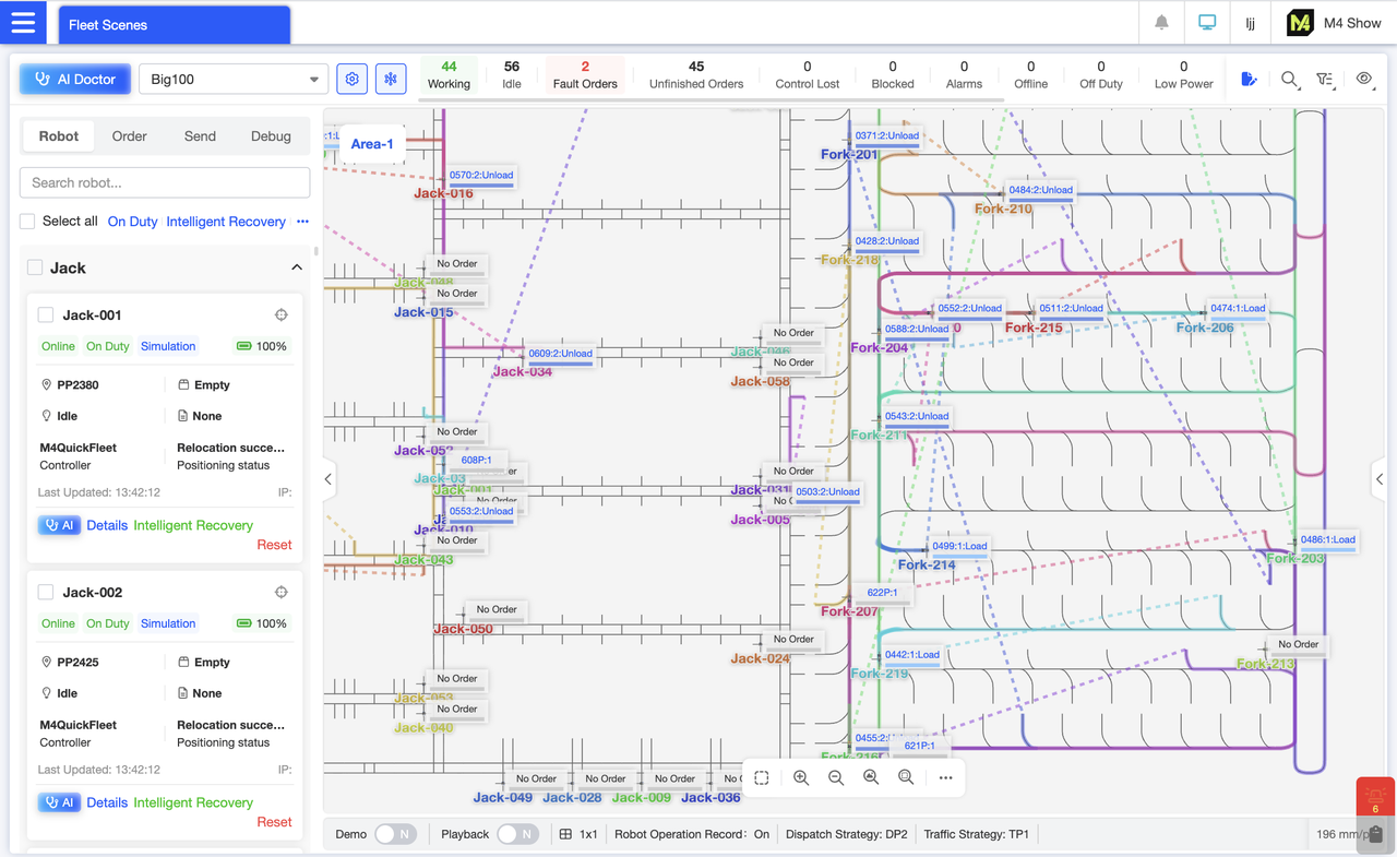
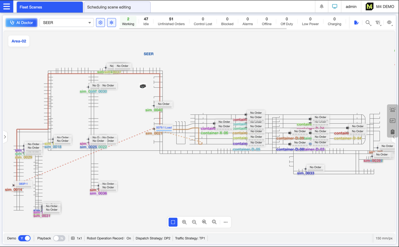
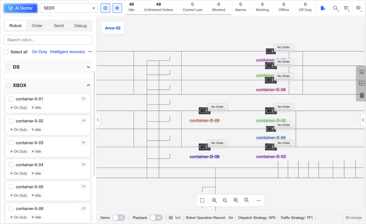
Overall Dispatch Operation Interface: The top section features a scene-switching dropdown menu and robot/scene status statistics. Robot cards are vertically arranged on the left for intuitive viewing of key robot information. The central map area displays the overall scene layout, real-time robot locations, task execution paths, and zones. The bottom status bar presents core dispatch parameters. Gain comprehensive oversight of the entire dispatch status.
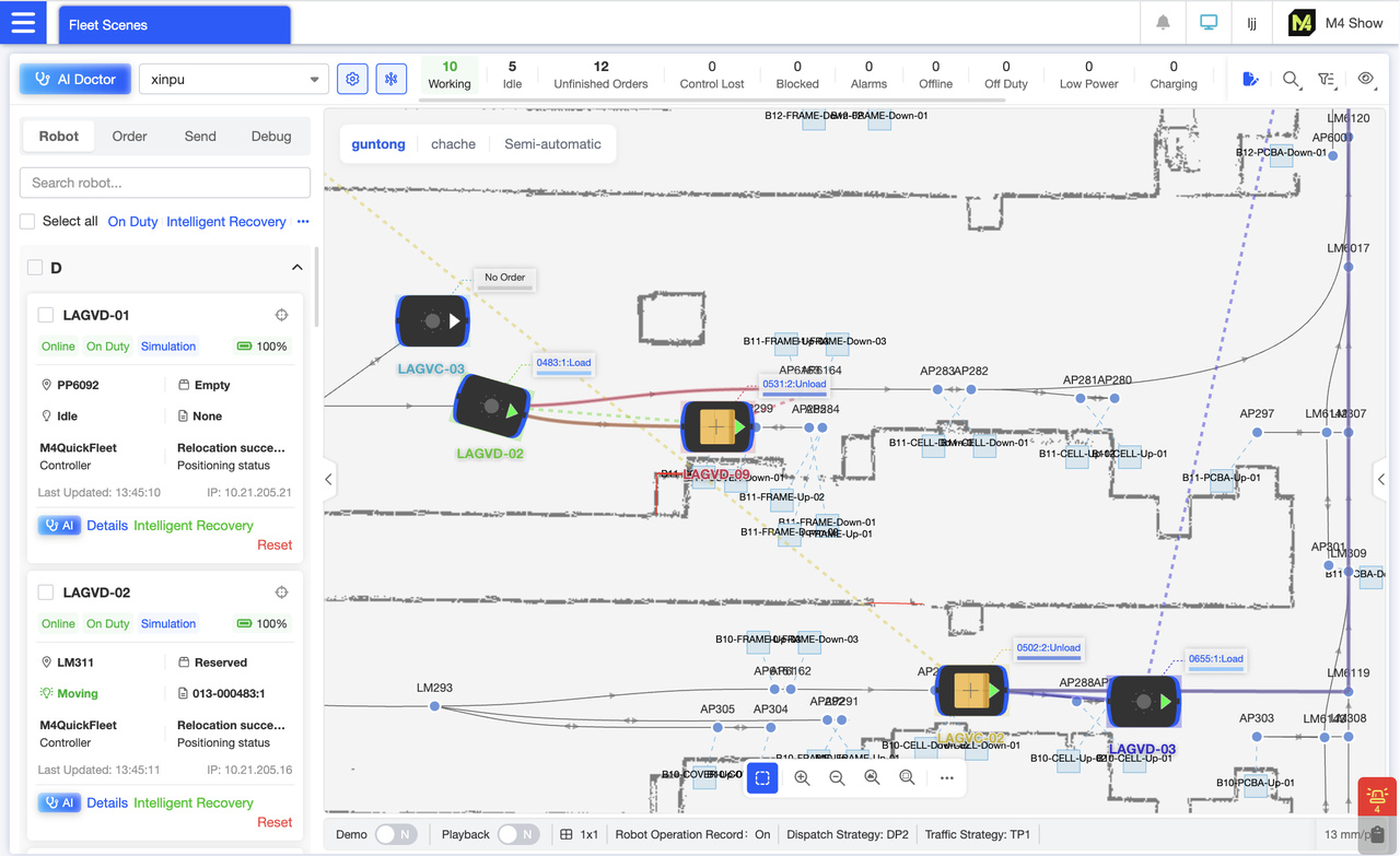
Zooming in on the map within the dispatch overview interface reveals more detailed robot transport status. Each robot displays an arrow indicating its forward direction. Robots operate in either empty or loaded states. Upon completing a pickup, a cargo marker appears on the robot, represented in the map as yellow cargo. While executing a delivery order, the card in the robot's upper-right corner displays the current order number being processed.
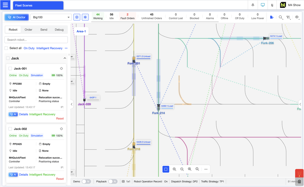
During execution, each robot maintains a continuous target indicator line extending to its endpoint. Additionally, polygons featuring the robot's theme color and transparency appear beneath the robot and ahead in its direction of travel, marking the traffic management resources it occupies along the path. These markers enable us to visually track each robot's objectives and observe the traffic management planning currently being executed.
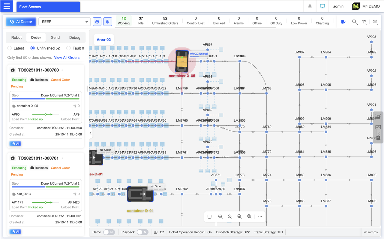
Uncompleted Delivery Order Card List: View real-time delivery order execution status, current step, pickup/drop-off target locations, and other key details. Quickly track core information for pending orders without clicking into details. Supports order cancellation, suspension, and instant access to AI diagnostics for this order.
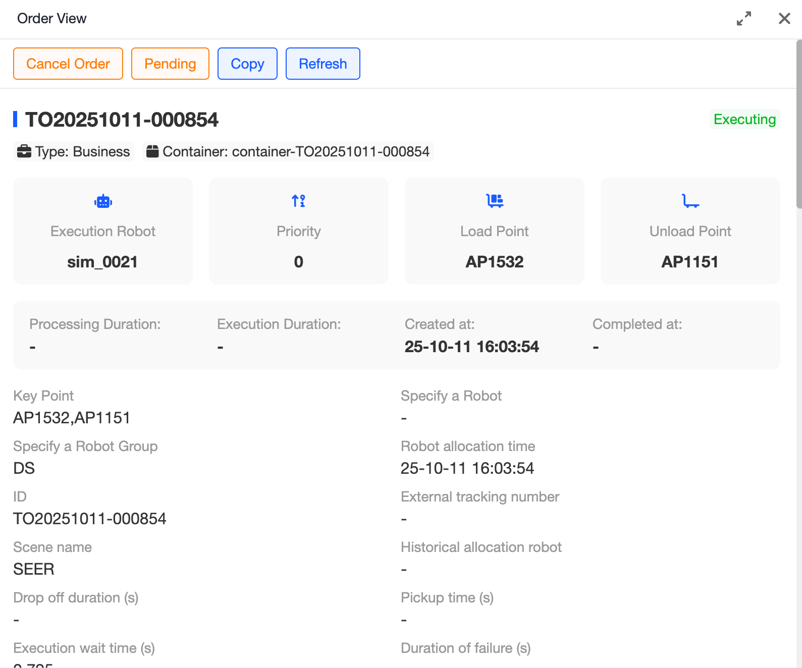
Order Details Page Comprehensively displays the entire waybill process, including order number, current status, order time, order type, pickup/delivery locations, and more. This enables you to fully trace the order execution process and quickly pinpoint issues.Click the top action buttons to cancel, suspend, or duplicate the order.
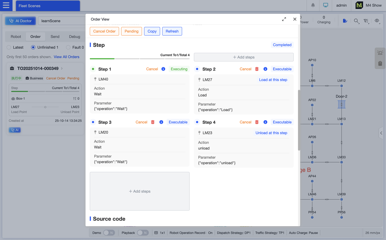
Order Details Page: Displays the total number of steps, whether the package has been sealed, the current step number, and completed steps. For each step, it shows the location, action, and parameters. Uncompleted steps can be canceled, deleted, or edited.If the step is critical, it will also show indicators for “Load at this step” and “Unload at this step.”
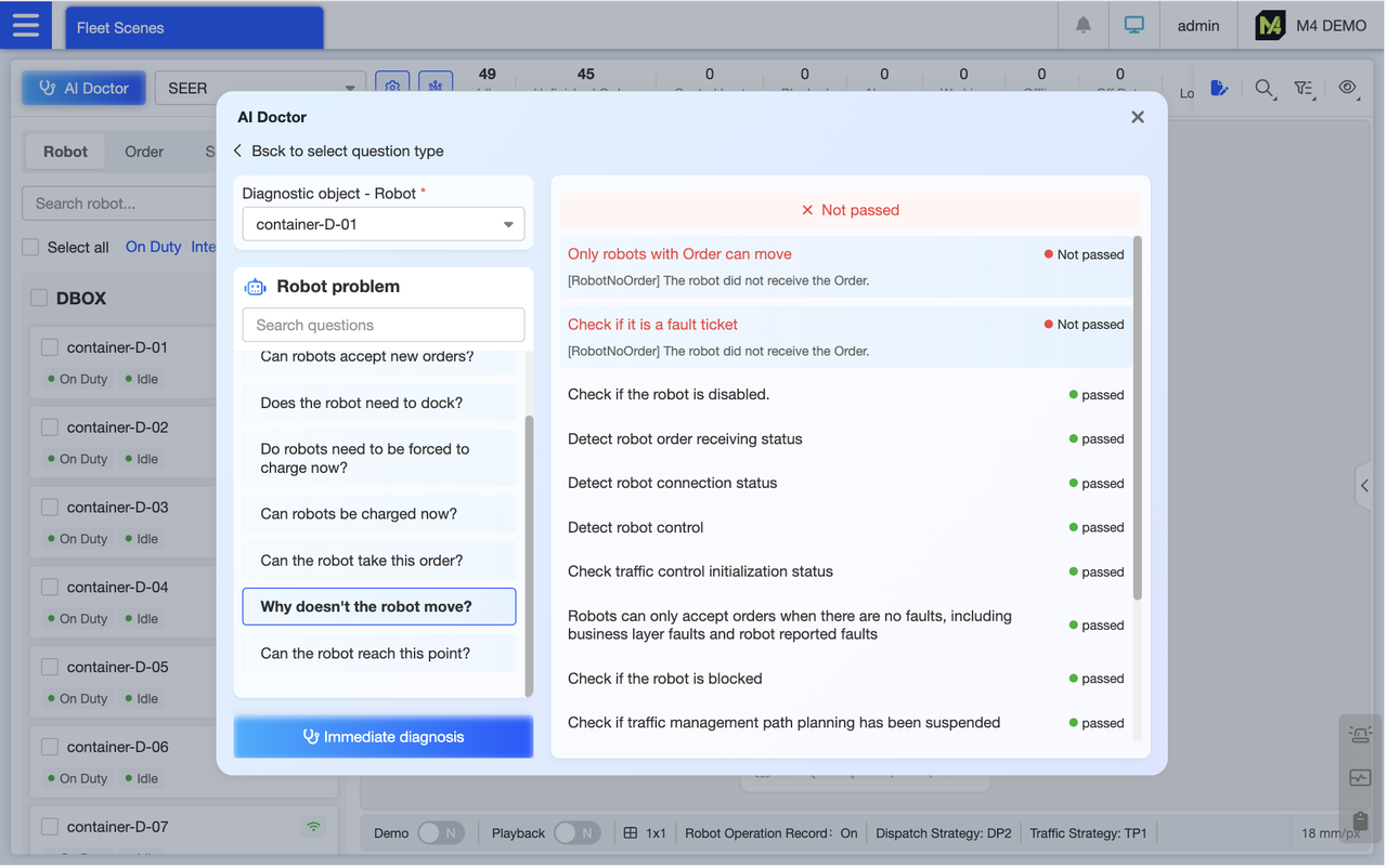
To diagnose robot issues using AI, simply select the robot and problem to diagnose. The system automatically detects key conditions relevant to the issue, presenting results as “Pass/Fail” for intuitive visualization. It also highlights specific reasons for failures and provides repair guidance.
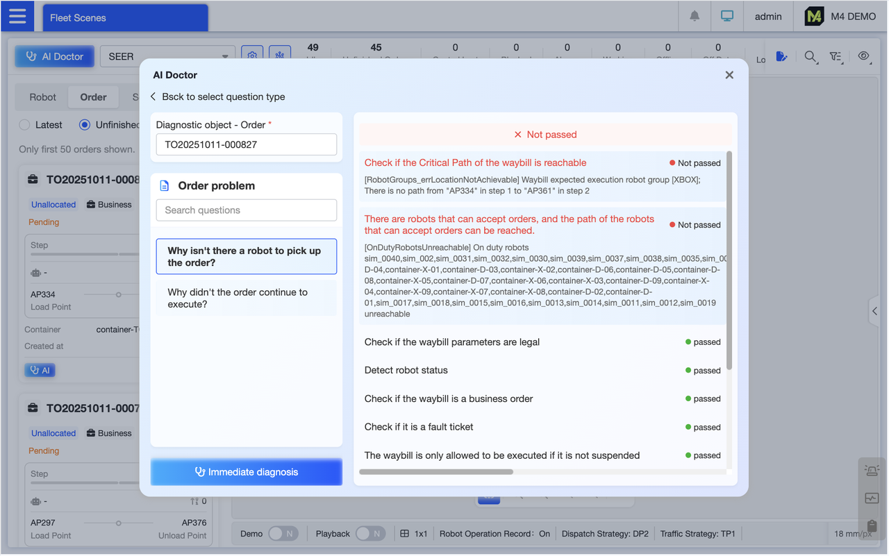
Issued an order but encountered an issue? Enter the specified order number and problem, and AI will help resolve your order concerns.
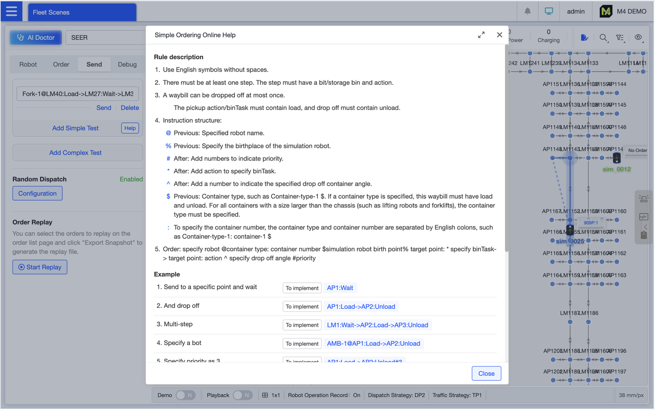
Simple Order Placement Online Help: Comprehensive guidelines for the entire order placement process (including format requirements, mandatory parameters, and restricted zones), paired with over 10 scenario-based examples. Click “To implement” on any example to instantly copy the command. Modify it as needed and execute the task instruction.
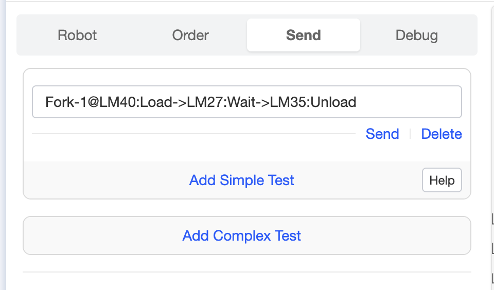
You can manually enter shipping instructions or find them through the Simple Shipping online help. Once the shipping instructions are written, click Execute to quickly complete the shipping process. This method is significantly faster than other ways of creating shipping orders.
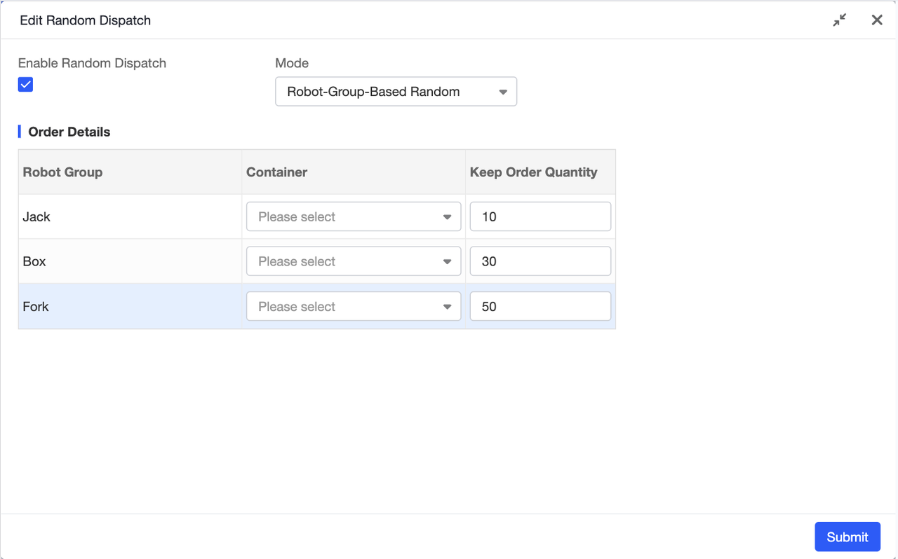
Assign tasks randomly to robot groups. Customize task volumes for each group to simulate varying workloads. The system automatically replenishes tasks for each group to maintain consistent workloads.
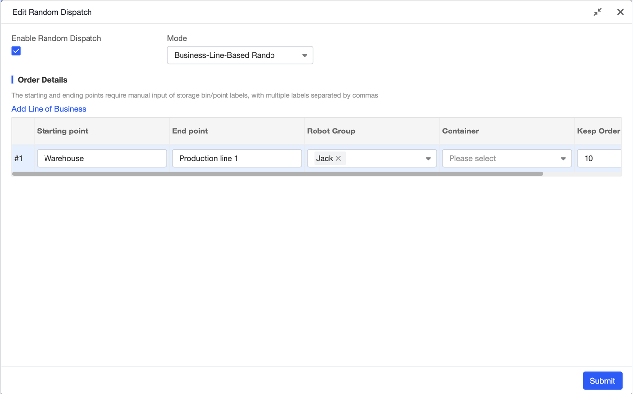
Randomly generate orders by business line. Enter the start and end labels for each business line to simulate task scenarios across different lines: input business line labels (e.g., “Inbound Line,” “Outbound Line”), and the system automatically matches corresponding start and end points to generate tasks. This accurately replicates real-world business scenarios, making it ideal for stress testing before launching new scenarios. You can also specify multiple labels at once—just separate them with commas for quick and convenient setup.
Demo Mode: Designed for exhibition settings, this feature automatically switches the interface perspective to monitor each robot's operation. Once activated, the scene locates and zooms in on an active robot, then transitions to another active robot, and so on. Ideal for visually demonstrating the system's overall performance to clients at trade shows.
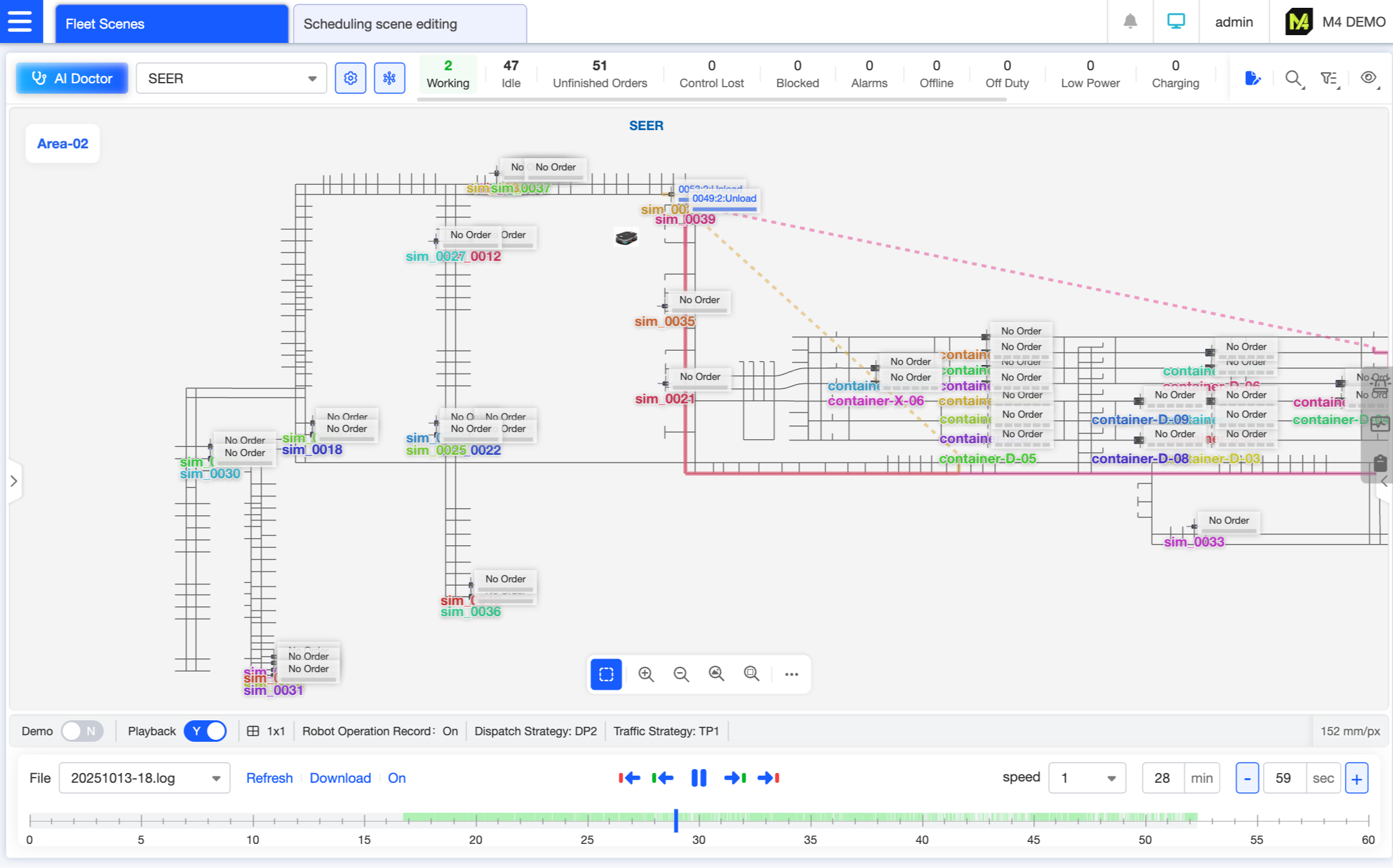
The system supports recording operational scenarios and enables playback review. Playback features two timelines: one for robot movements and another for alerts. Users can quickly switch between the previous/next frame of robot activity or alerts via buttons. Common functions like playback speed adjustment and time jumping are supported. During playback, users can drag the timeline to locate any moment, clearly displaying the robot's position, order status, and abnormal events at that time, facilitating the tracing of issue occurrence processes.
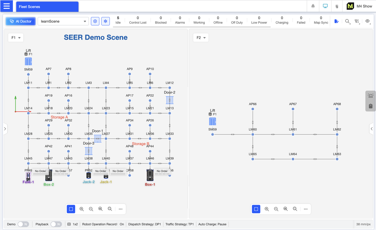
Map split-screen view enables side-by-side comparison of performance across different zones. For example, monitor the first floor on the left while viewing the second floor on the right to contrast robot density, order progress, and congestion levels across areas.
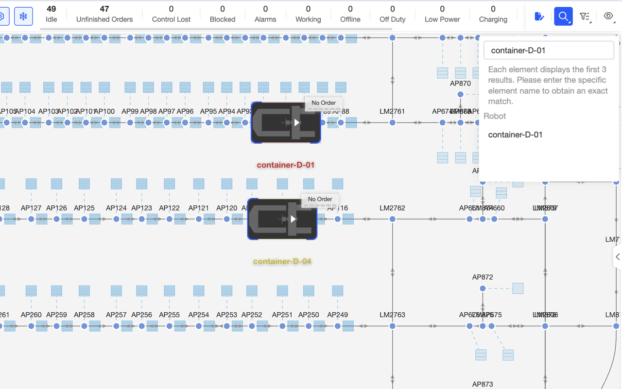
Searching for map elements allows you to find points, paths, and other features across all scenes. After entering your search query and pressing Enter, the map will highlight the search results for easy location. If no results are found, the system will display a message indicating no search results were found.
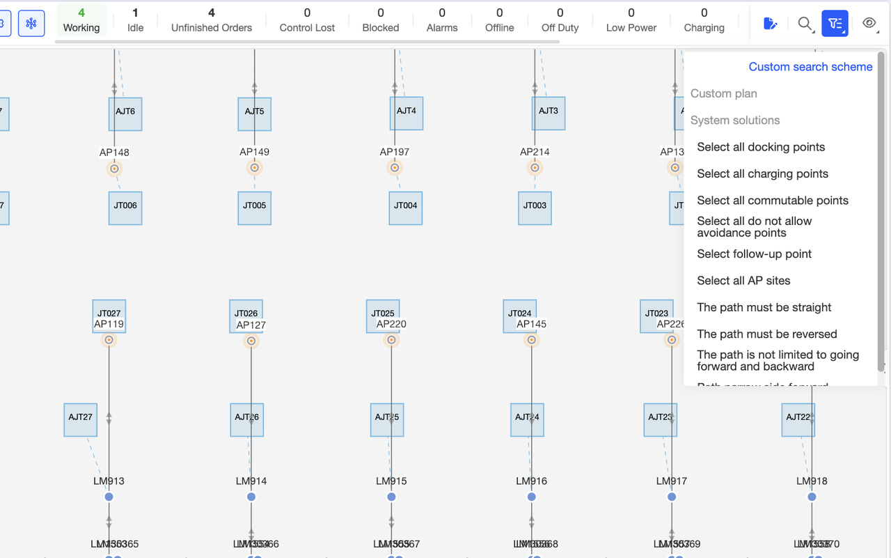
You can perform bulk searches for elements with specific attributes using the system's preset schemes. Click any scheme in the system, and the system will automatically filter and highlight matching elements. This allows you to quickly locate target elements before proceeding with subsequent operations such as bulk settings.
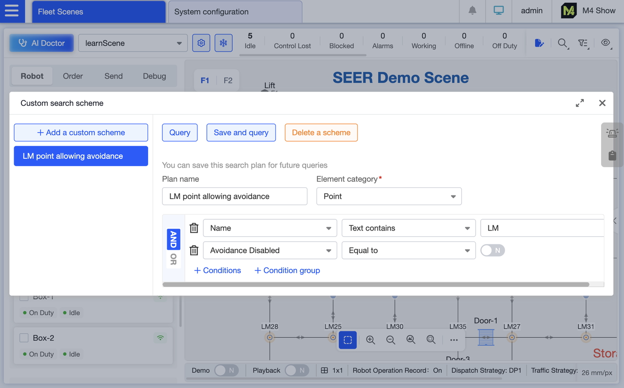
Support custom search profiles for batch searches. Set your own filtering criteria, save them as custom profiles, and reuse them directly next time to meet personalized bulk query needs.
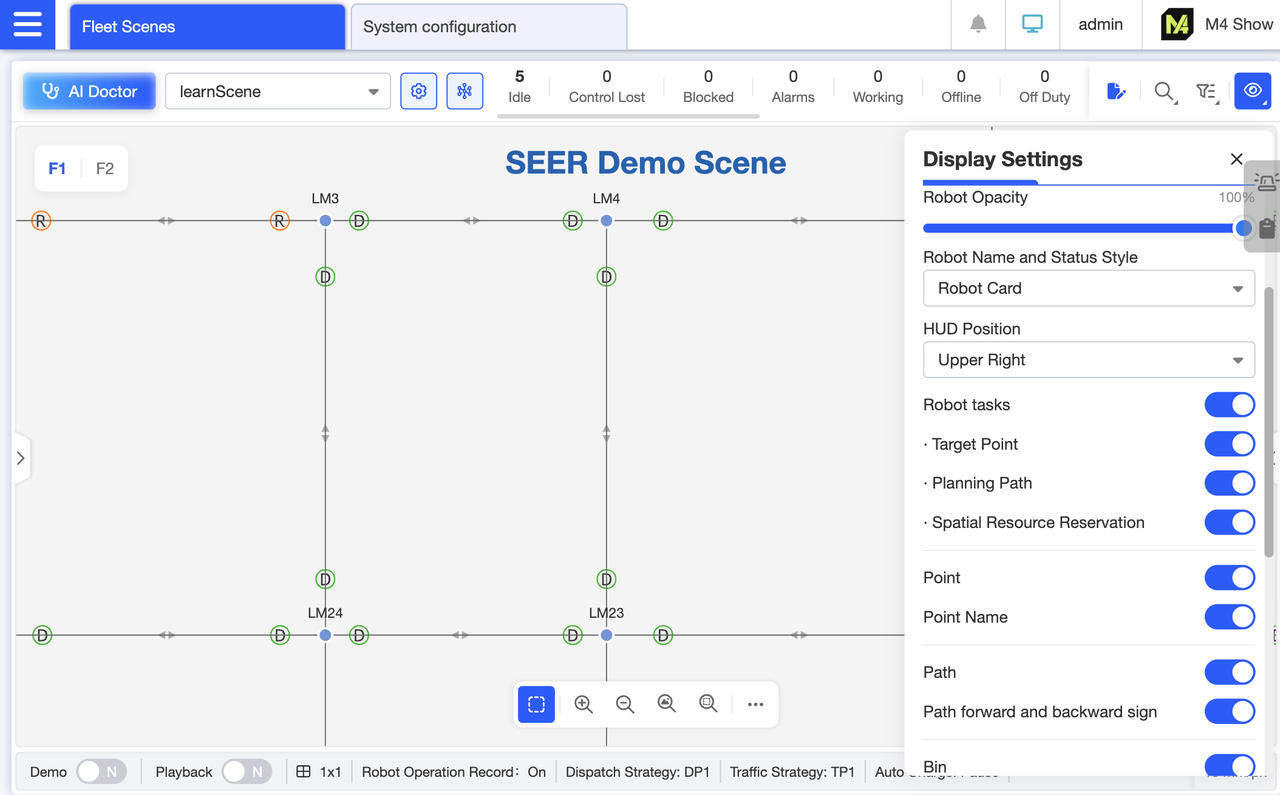
Display path direction indicators (forward/reverse). The DR indicator on each path shows whether forward or reverse movement is configured: D denotes forward, R denotes reverse. This visually distinguishes the robot's navigable direction, enabling rapid identification of issues like “incorrect path direction configuration” during debugging and reducing troubleshooting time.
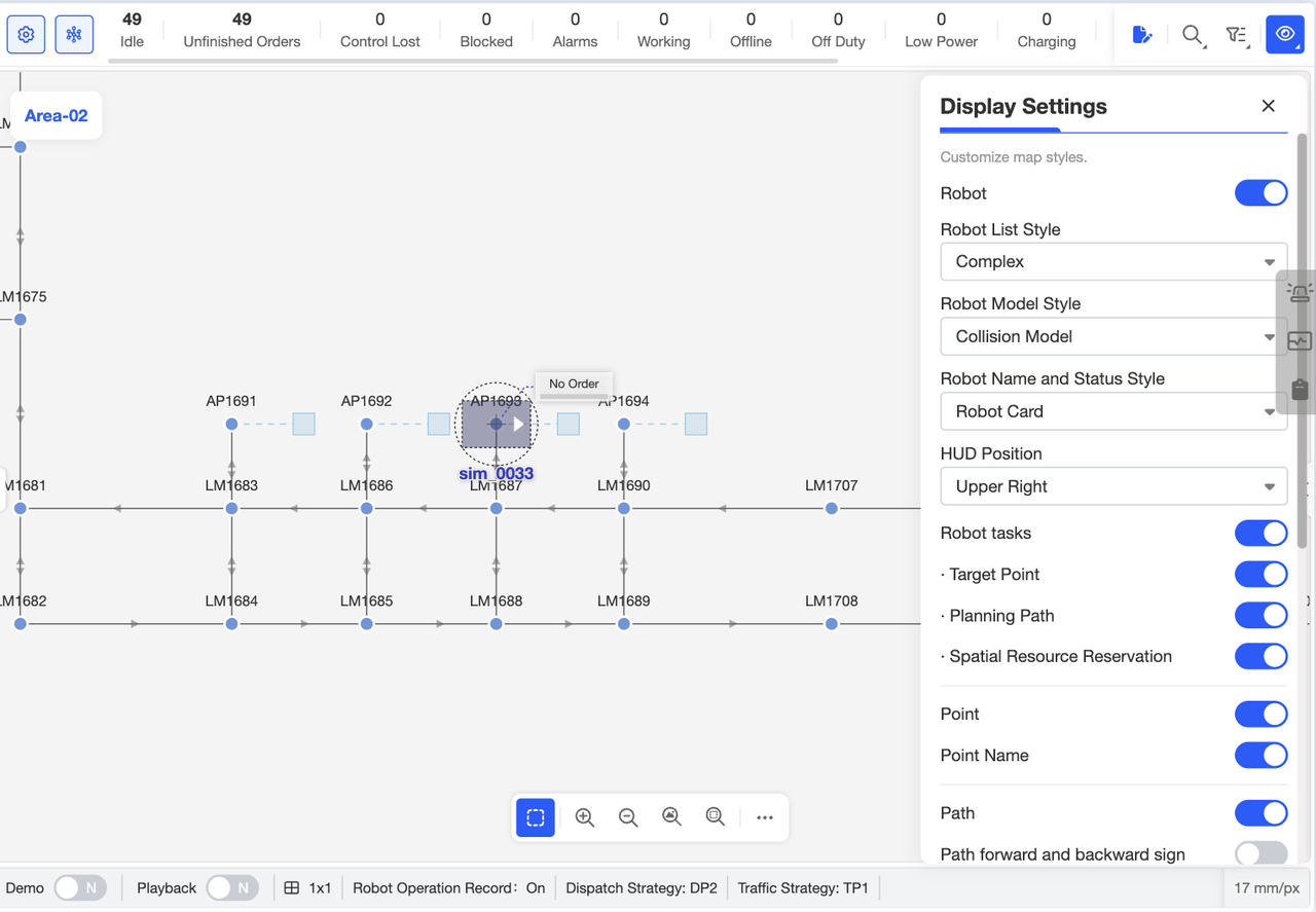
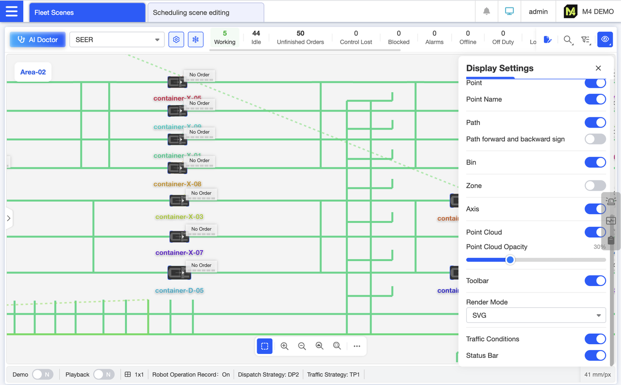
Through the display settings, you can control the visibility and styling of map elements. Customize these settings based on your priorities—whether you prefer simple robot cards or complex ones, or wish to adjust point cloud opacity. This allows the map to display only the information that matters to you, resulting in a cleaner interface.
The robot cards on the left can be switched to a simplified card view by selecting “Simple” in the display settings. This makes the page cleaner when there are many robots, allowing more robots to be displayed.
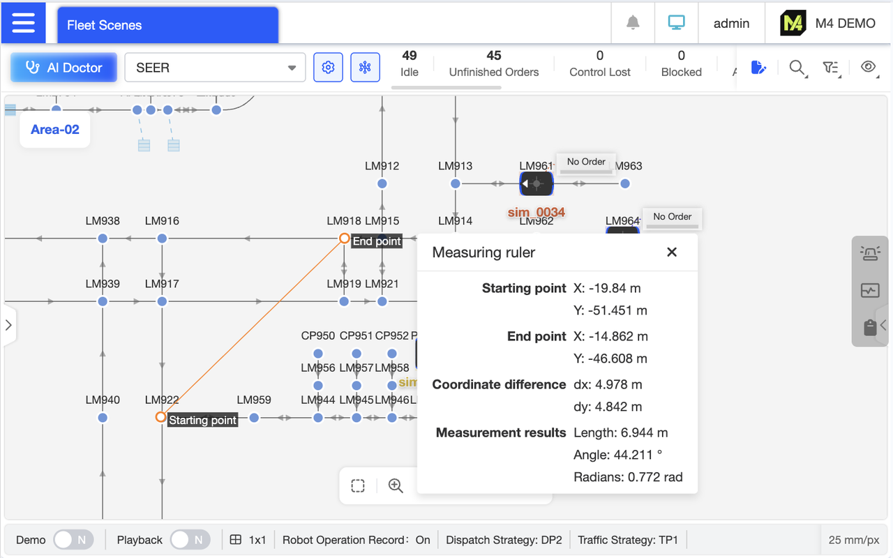
Map surveying provides starting and ending coordinates, along with coordinate differences, length, and angle information. Measurement results can also be copied directly for convenient recording of critical survey data.
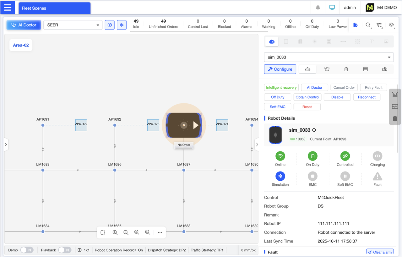
Robot Details Panel Displays real-time robot status and enables quick actions such as rejecting orders, intelligent recovery, and reset. Categorizes and shows fundamental information including robot storage locations, alerts, and positions. Clicking category icons allows instant navigation to corresponding sections for rapid access to robot details.
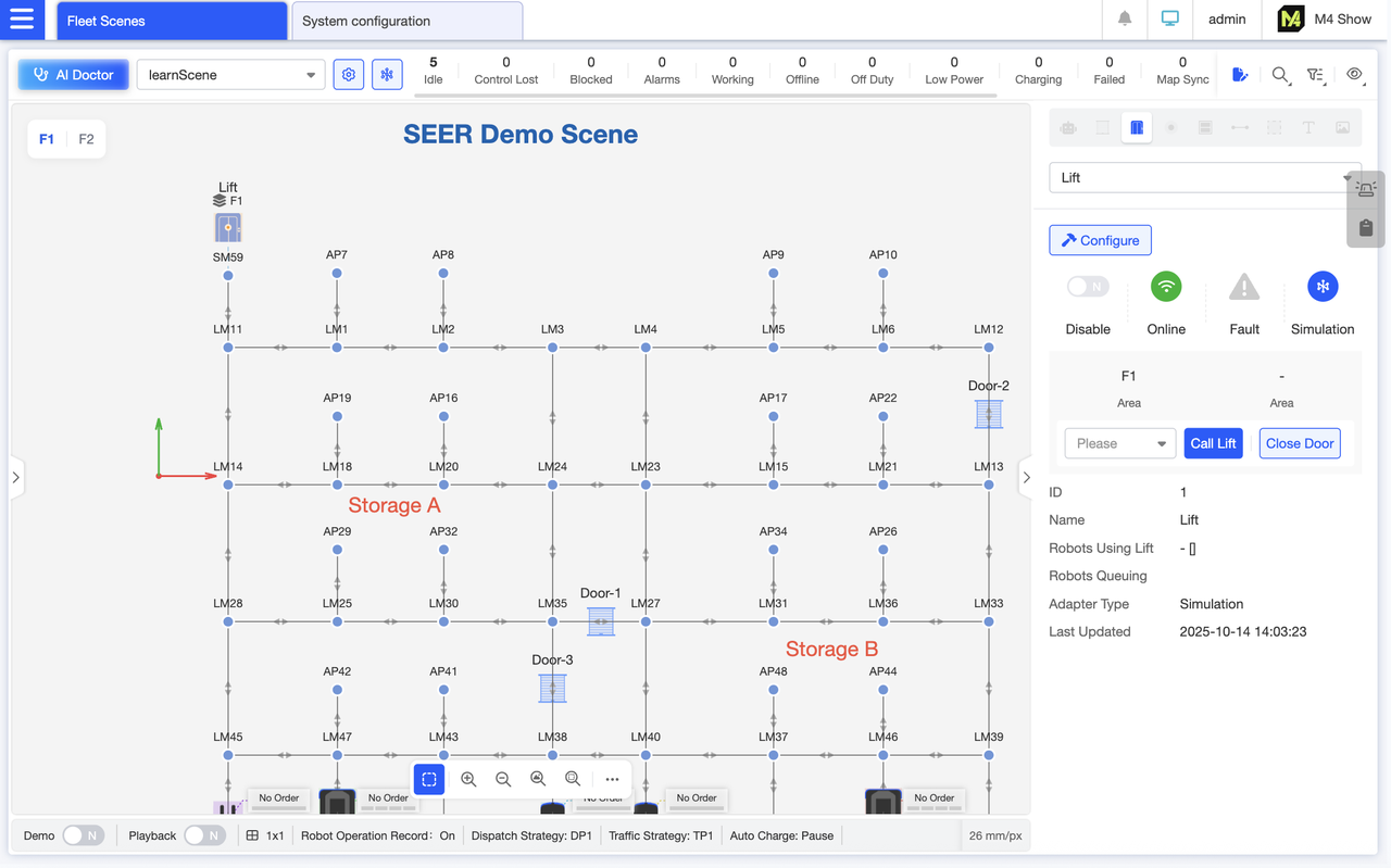
lift Details Panel: Displays lift status (online, malfunction) and basic information. Enables remote control via buttons to call the lift to a specific floor or close its doors, eliminating the need for on-site operation and improving dispatch efficiency.
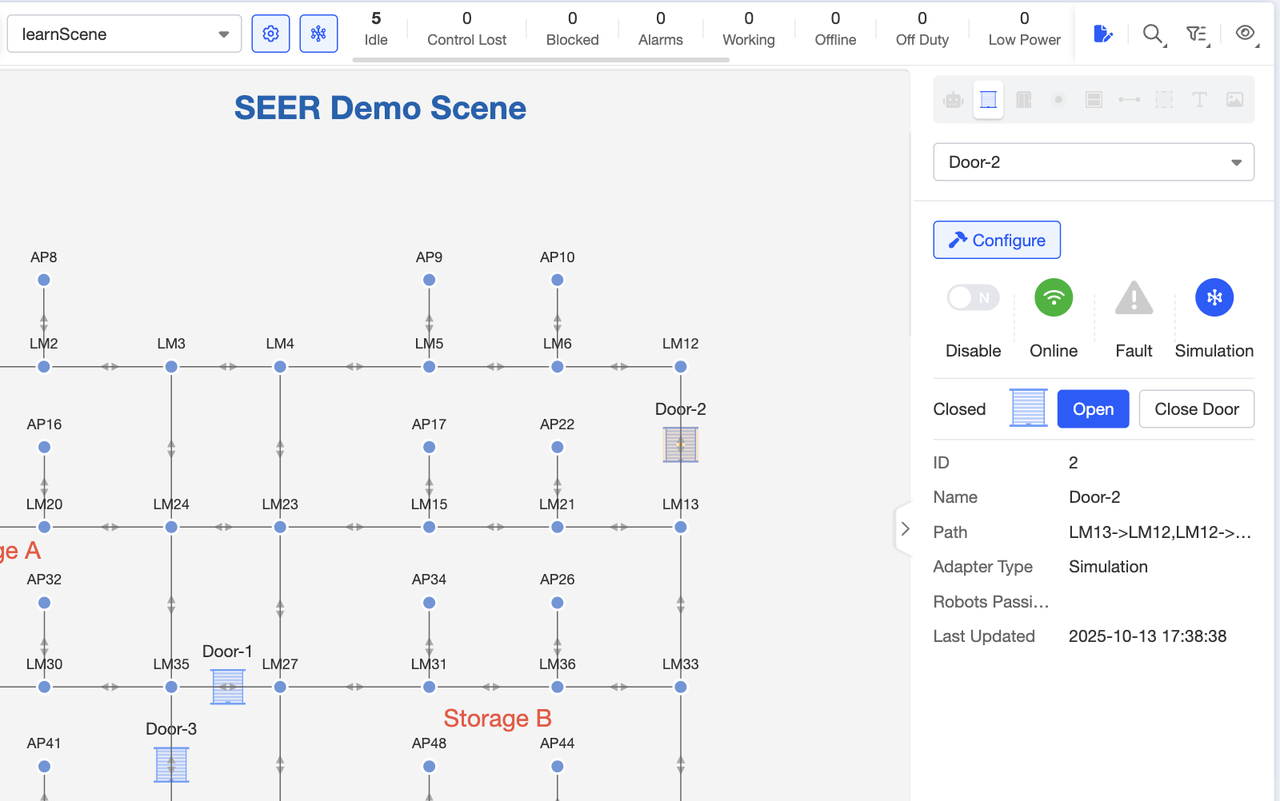
Door Details Panel: Displays door status and information, and enables quick opening and closing operations.
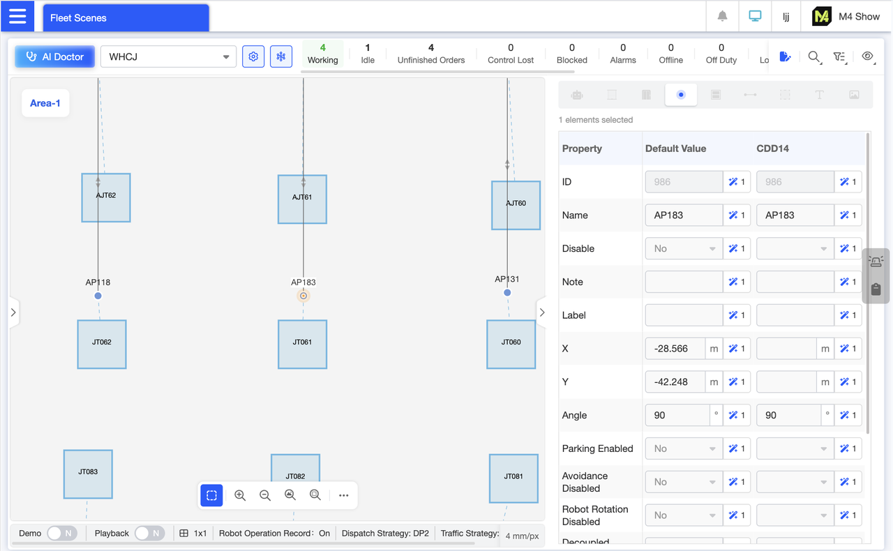
View the properties of a single point. Property names and values are displayed in a tabular format, with default values and robot group values shown in separate columns. The left column displays default values, while the right column lists customized values for each robot group, allowing you to visually compare whether different robot groups' values differ from the default. Additionally, units are provided as suffixes for each property.
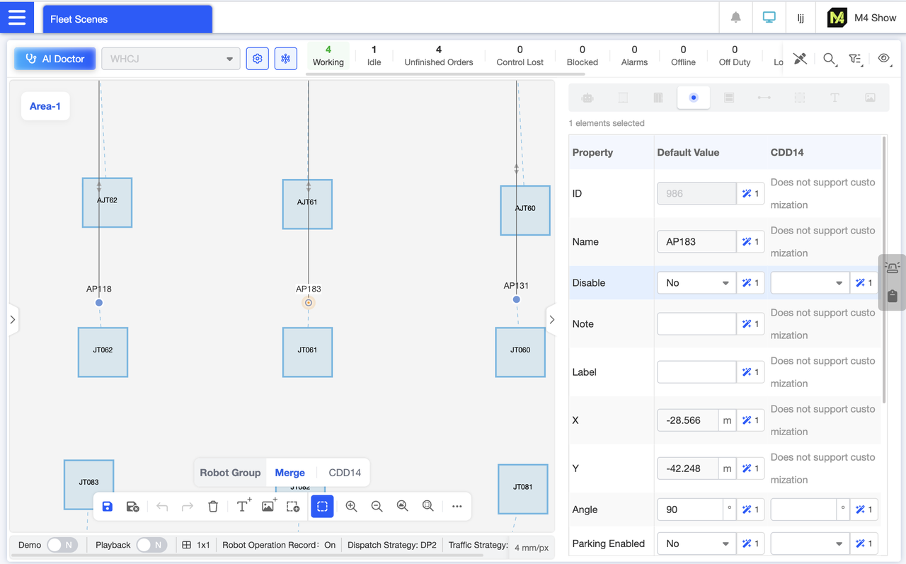
In map editing mode, when editing individual points, values can be customized for different robot groups. Attributes that cannot be customized are clearly marked, accommodating the distinct requirements of various robots.
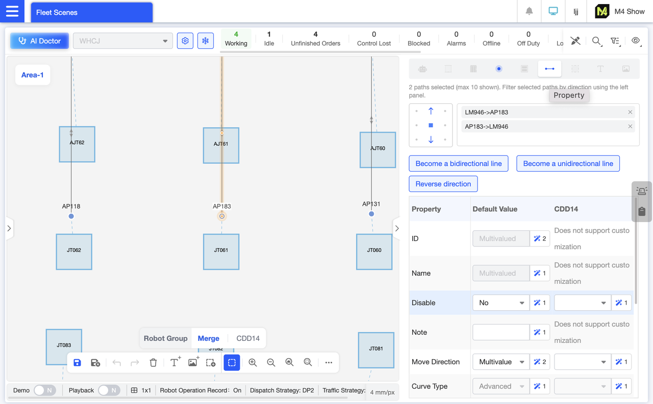
In Map Editor mode, when editing multiple paths, the crosshair selector at the top of the interface displays the direction of the selected path. You can further filter path directions by clicking. Additionally, buttons allow you to quickly convert one-way paths to two-way paths, two-way paths to one-way paths, or reverse the direction. Within the table, you can customize settings for paths across different robot groups to meet their distinct requirements. Attributes that cannot be customized will be marked accordingly.
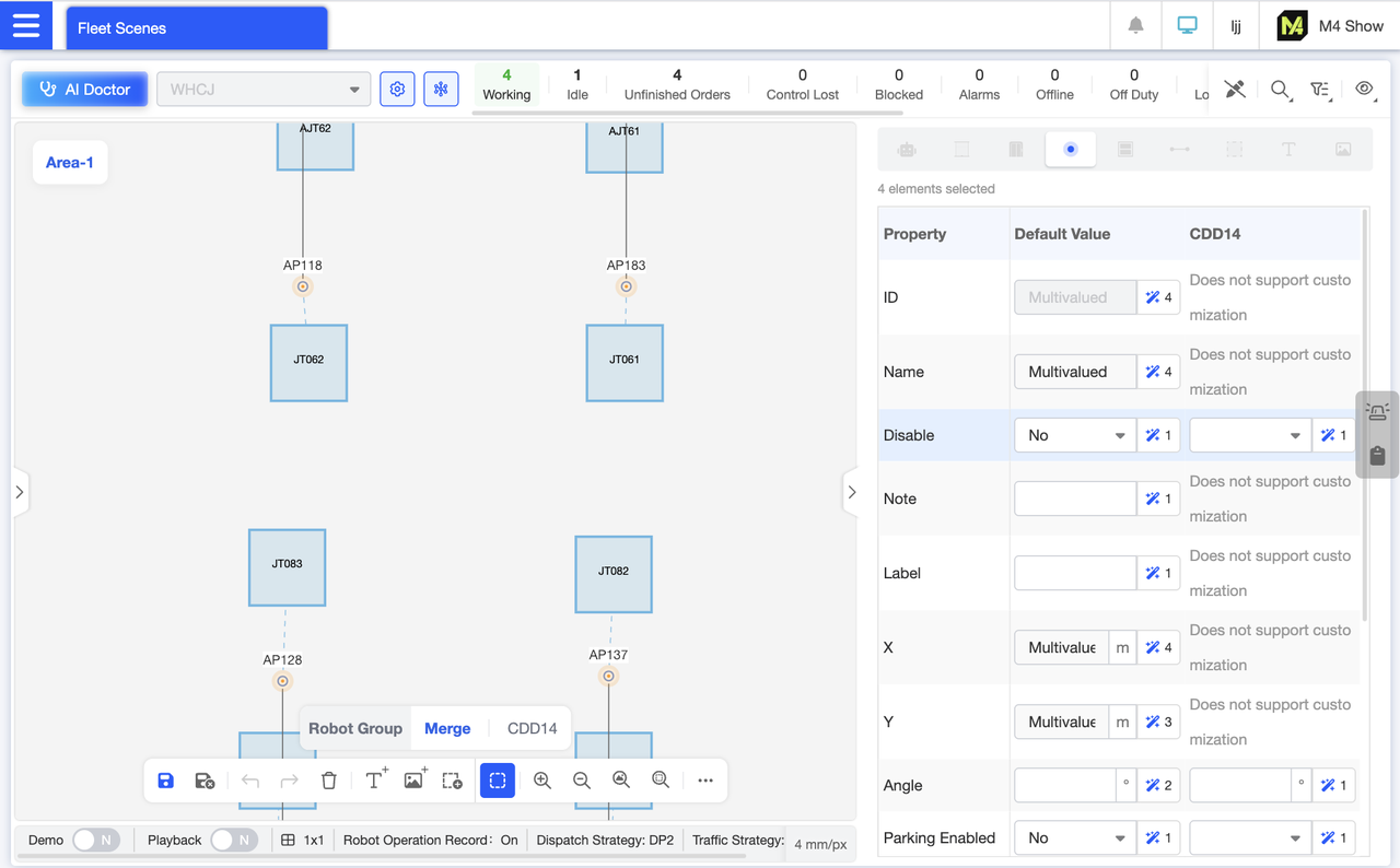
In map editing mode, select multiple points and open the element details panel. If the attribute values differ across multiple points, they will display as “multiple values.” If all points share the same attribute value, that value will be shown directly. For example, since all 7 points are not disabled, the disable attribute value is “No.” Following each attribute value is a number indicating how many distinct instances of that attribute exist across these elements. Modify the attribute value in the editable input field to batch-set the attributes for these points.
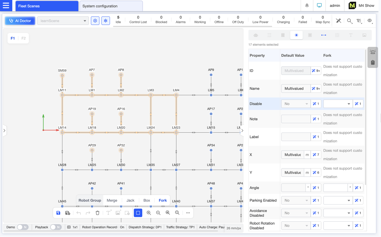
In Map Editor mode, you can directly modify point attributes for grouped maps. Switch to the “Fork” Group Map view to ensure edited point attributes apply only to the forklift group, leaving other robot groups unaffected—enabling clearer group management.
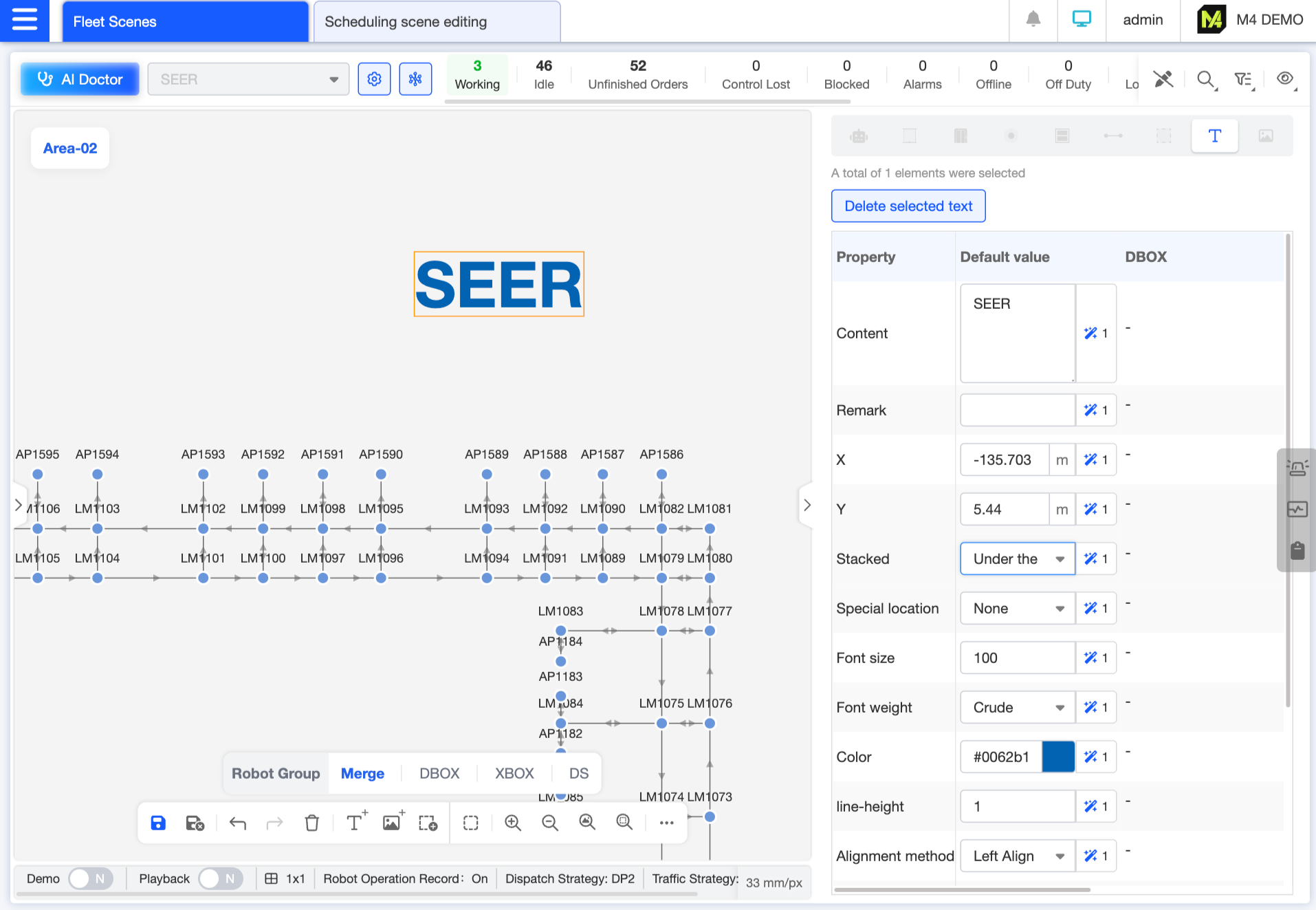
Insert text, adjust its size, color, and other properties as needed, and use it to decorate the map. For example, you can add a map title at the top to enhance readability or make it more suitable for display purposes.
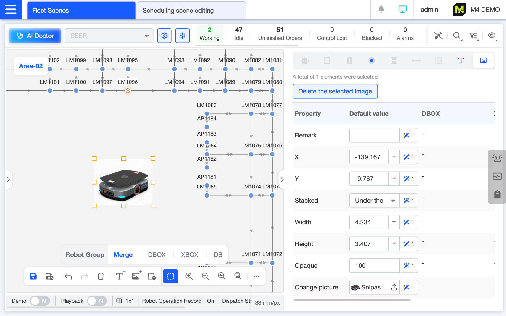
Insert images and resize them appropriately to decorate the map. You may upload actual photos of the scene or schematic diagrams (e.g., “shelf layout diagrams,” “door control panel diagrams”). After scaling and adjusting, place them at corresponding locations to help on-site personnel understand map symbols by referencing physical objects.
Enable real-time traffic display in the settings. The map uses color-coded paths to indicate congestion levels (green = clear / red = congested), allowing for an intuitive assessment of overall road conditions in the current dispatch scenario.
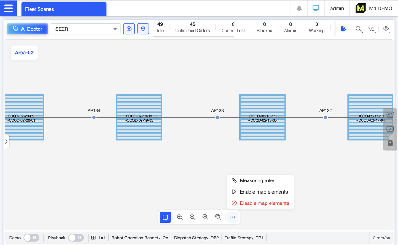
No need to enter edit mode—quickly enable or disable map elements: Select the corresponding element, then tap “Enable” or “Disable Map Element” in the “More” section of the bottom toolbar for instant operation.
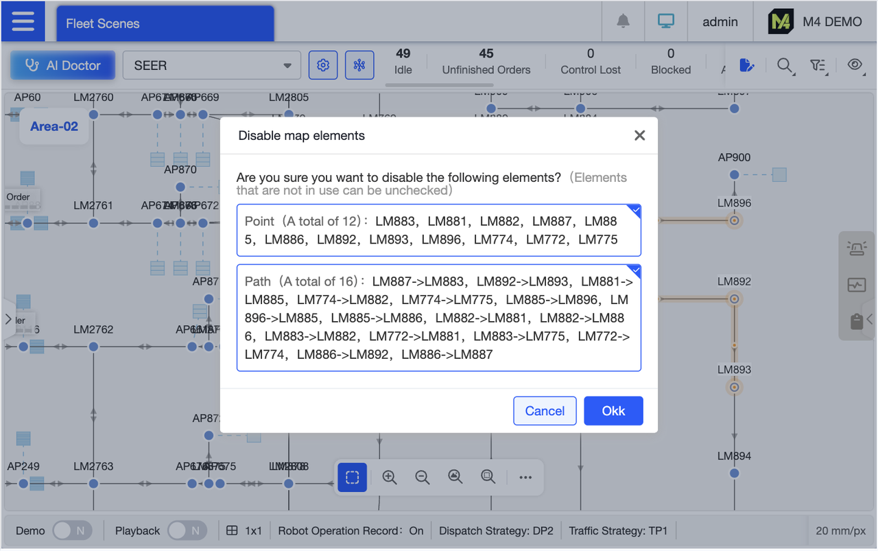
When multiple elements are selected, you can further choose the categories of elements to disable in the dialog box. For example, if you only want to disable paths but not points, simply uncheck the points option.
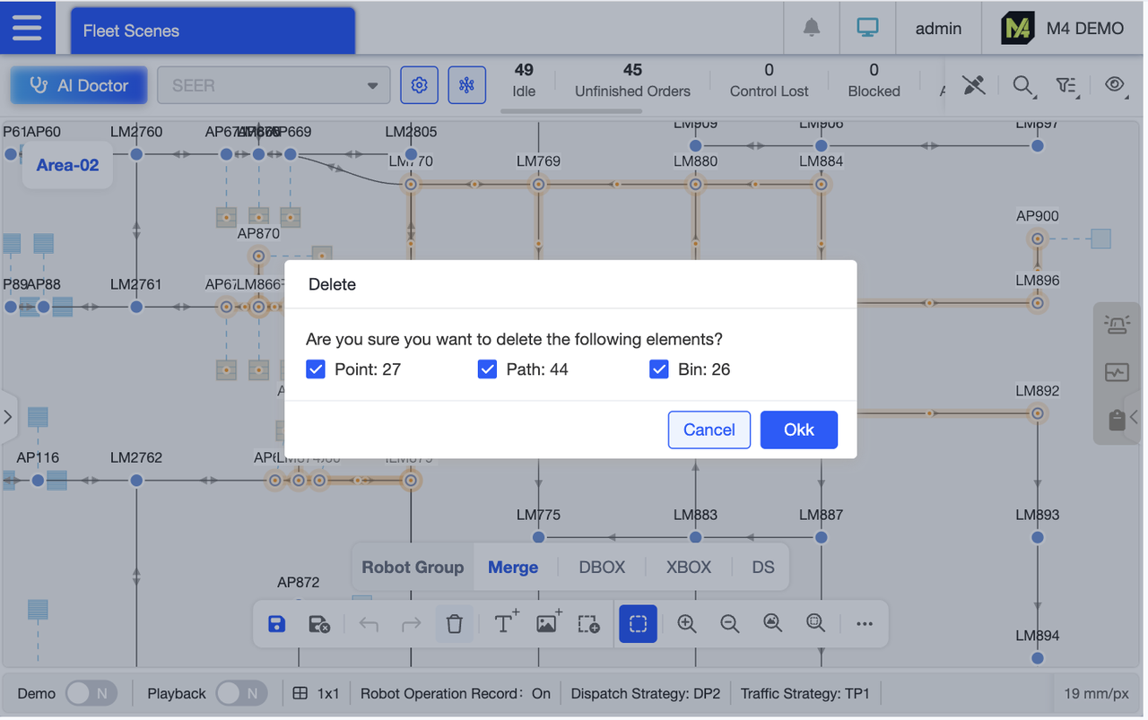
Supports batch deletion of map elements. Select multiple unnecessary elements (such as obsolete points), click “Delete,” and confirm to clear them all at once, avoiding the tedious process of deleting them individually. If multiple element types are selected, you can further specify the types to delete in the dialog box for precise control.
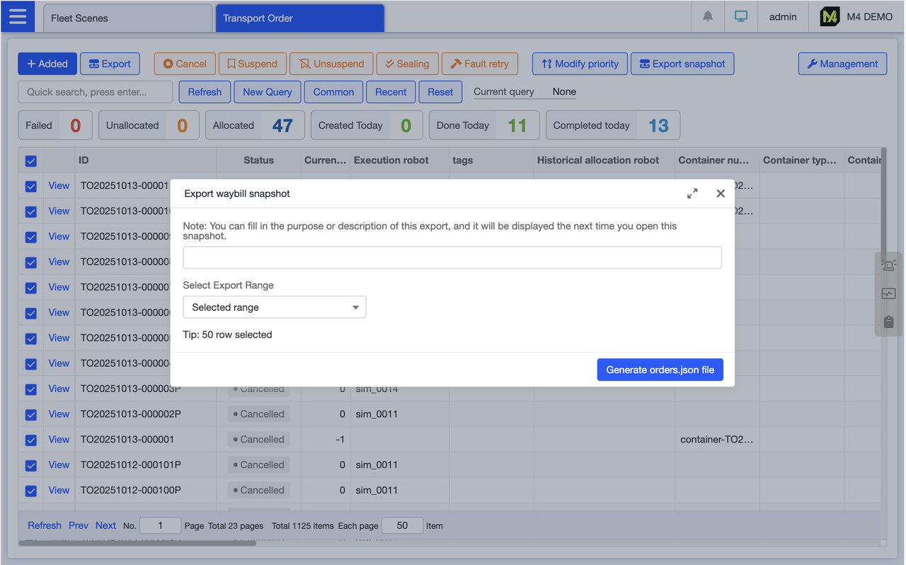
On the shipping list page, select the target shipping order, click Export Snapshot, and fill in the remarks during export for easy reference when importing. Click Generate File to export the shipping order file as a snapshot. The exported file will have the order.json extension.
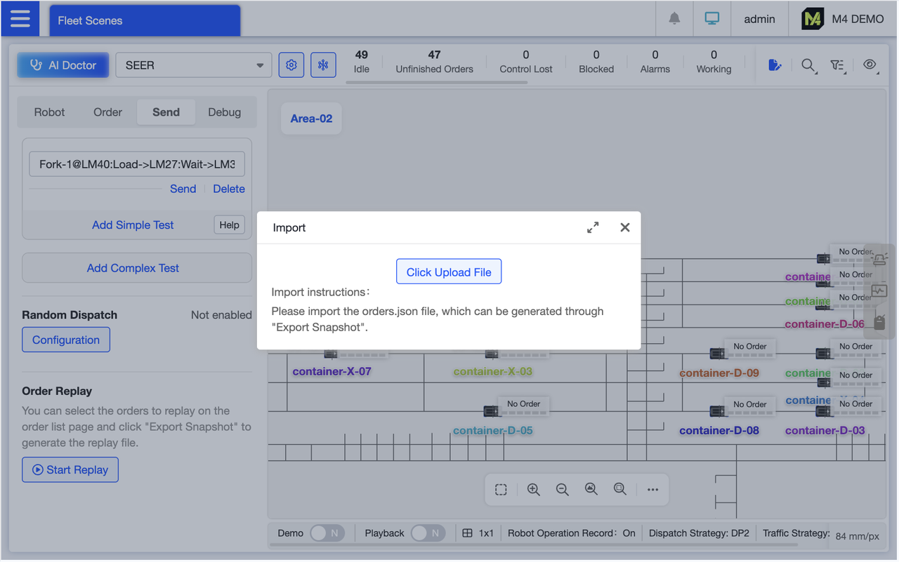
After exporting the waybill snapshot, click Start Replay in the waybill replay area at the bottom of the order page and upload the exported waybill snapshot file.
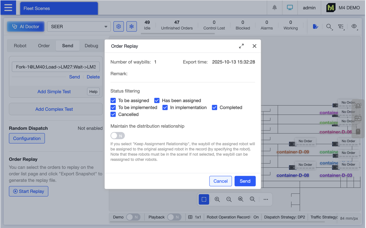
The system parses the waybill snapshot file, detects the number of waybills, export time, and remarks, and displays them on the page. Users can filter by waybill status and enable “Maintain Assignment Relationships.” When enabled, this indicates that waybills already assigned to robots will continue to be executed by those robots during replay if they are available. Clicking “Execute” generates new waybills, enabling reuse of waybill logic for debugging and verifying execution outcomes.
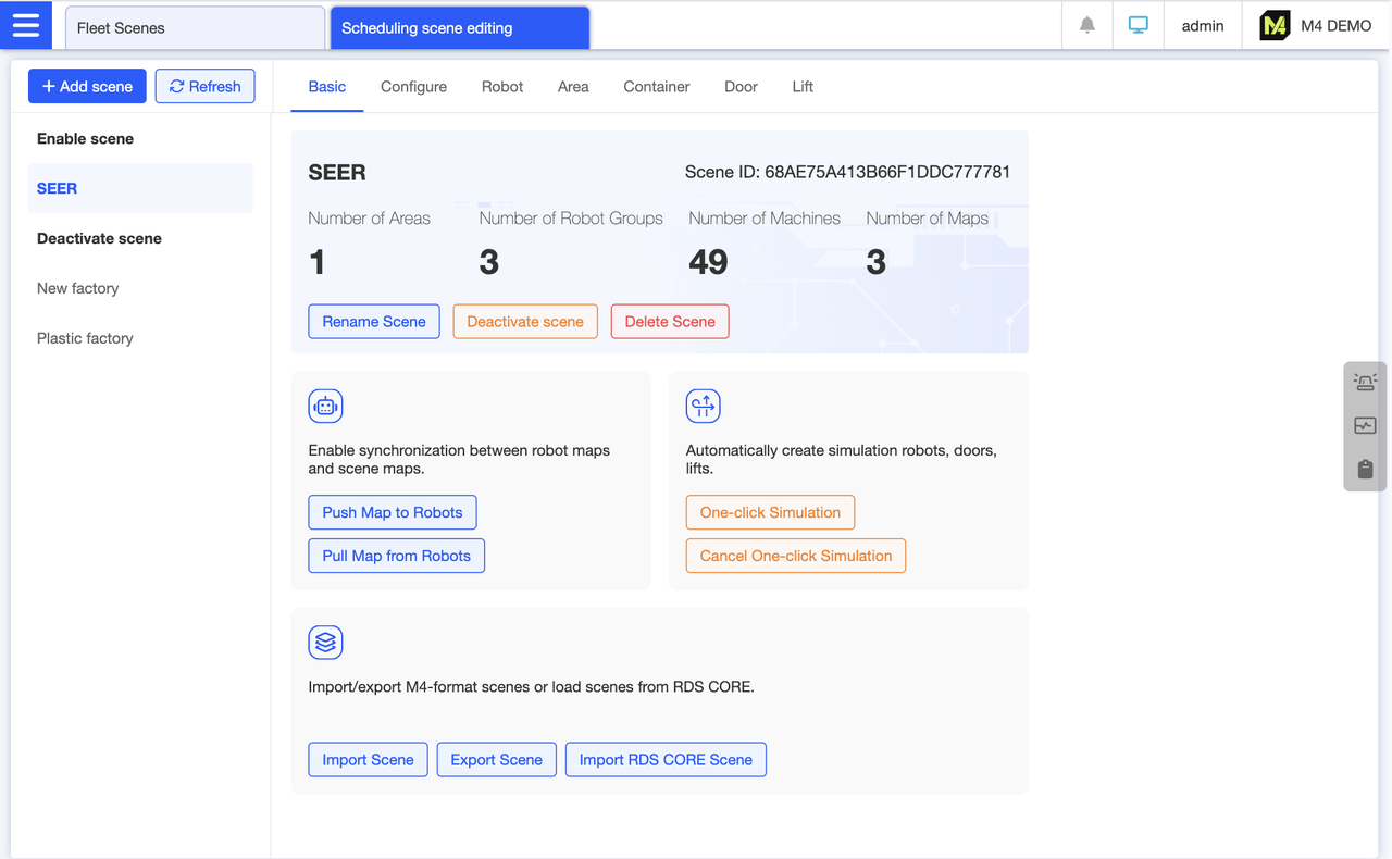
Scene Basic Information Overview: The left pane displays the complete scene list, including both enabled and disabled scenes. The central section shows scene names, scene IDs, regions, robot groups, robots, and map counts. You can also perform scene-related operations here, such as renaming, disabling, deleting, importing, or exporting scenes. Map push and pull functions are also managed here. After importing a scene, you can initiate or cancel one-click simulation directly from this section.
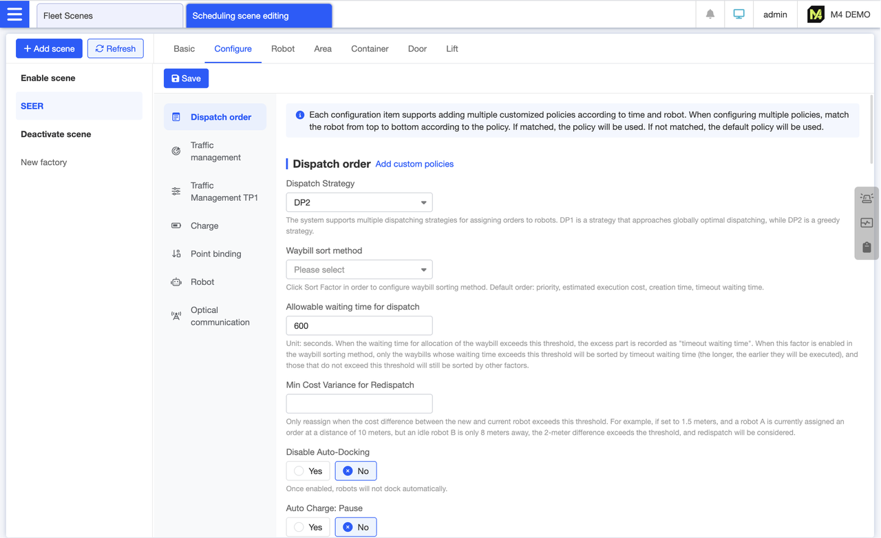
All configuration items for the categorized display scenarios are listed here. Click the left menu to quickly navigate to the corresponding category. We strive for fewer yet precise configuration items, each accompanied by annotations for clarity.
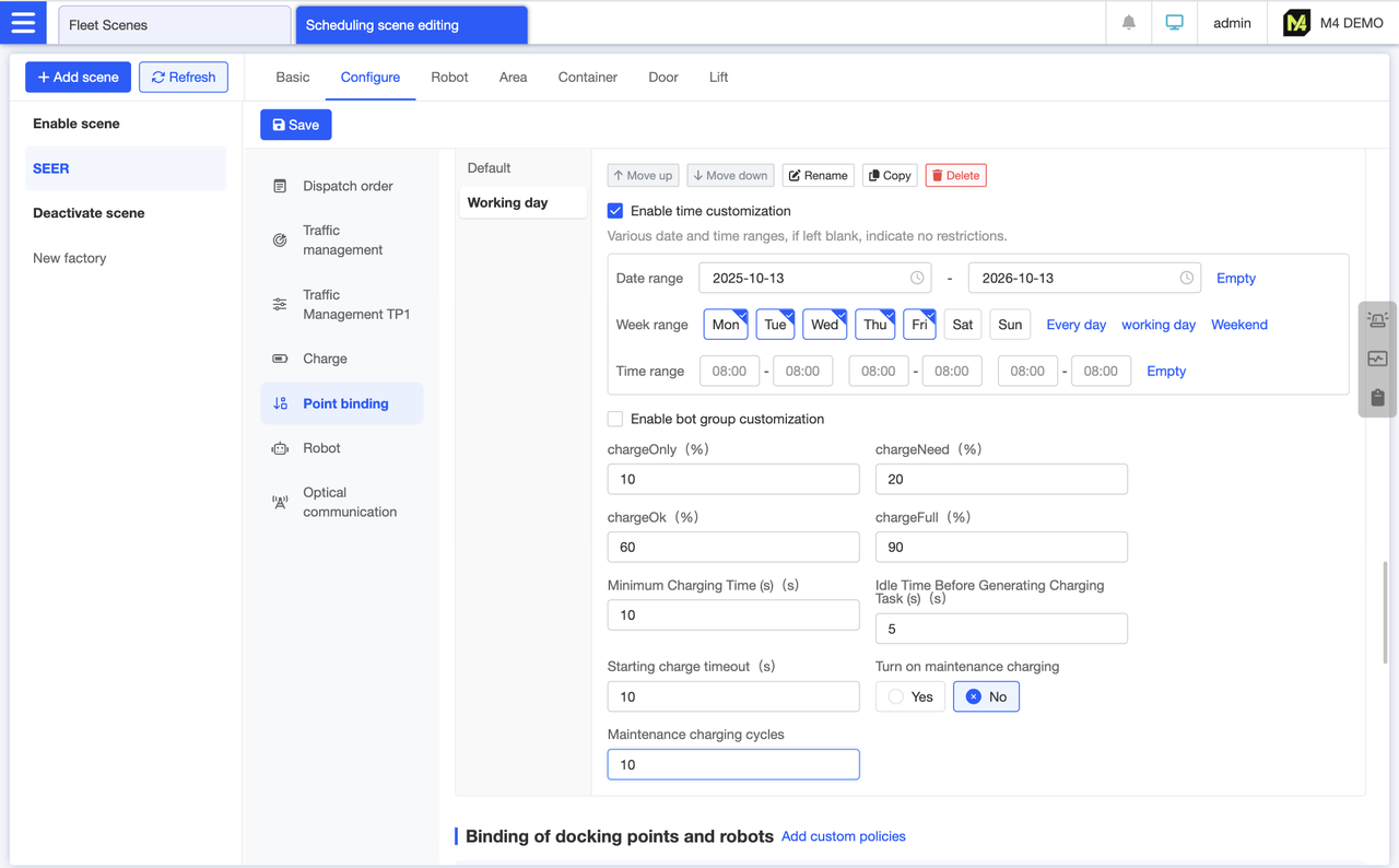
The settings on the configuration page represent the default policy. To customize settings for different times or robot groups, click “Add Custom Policy” under the corresponding configuration section on the interface. For example, you can add a weekday policy where the robot's chargeNeed is set lower from Monday to Friday, reverting to the default value on weekends. This allows the robot to have more operational time during weekdays.
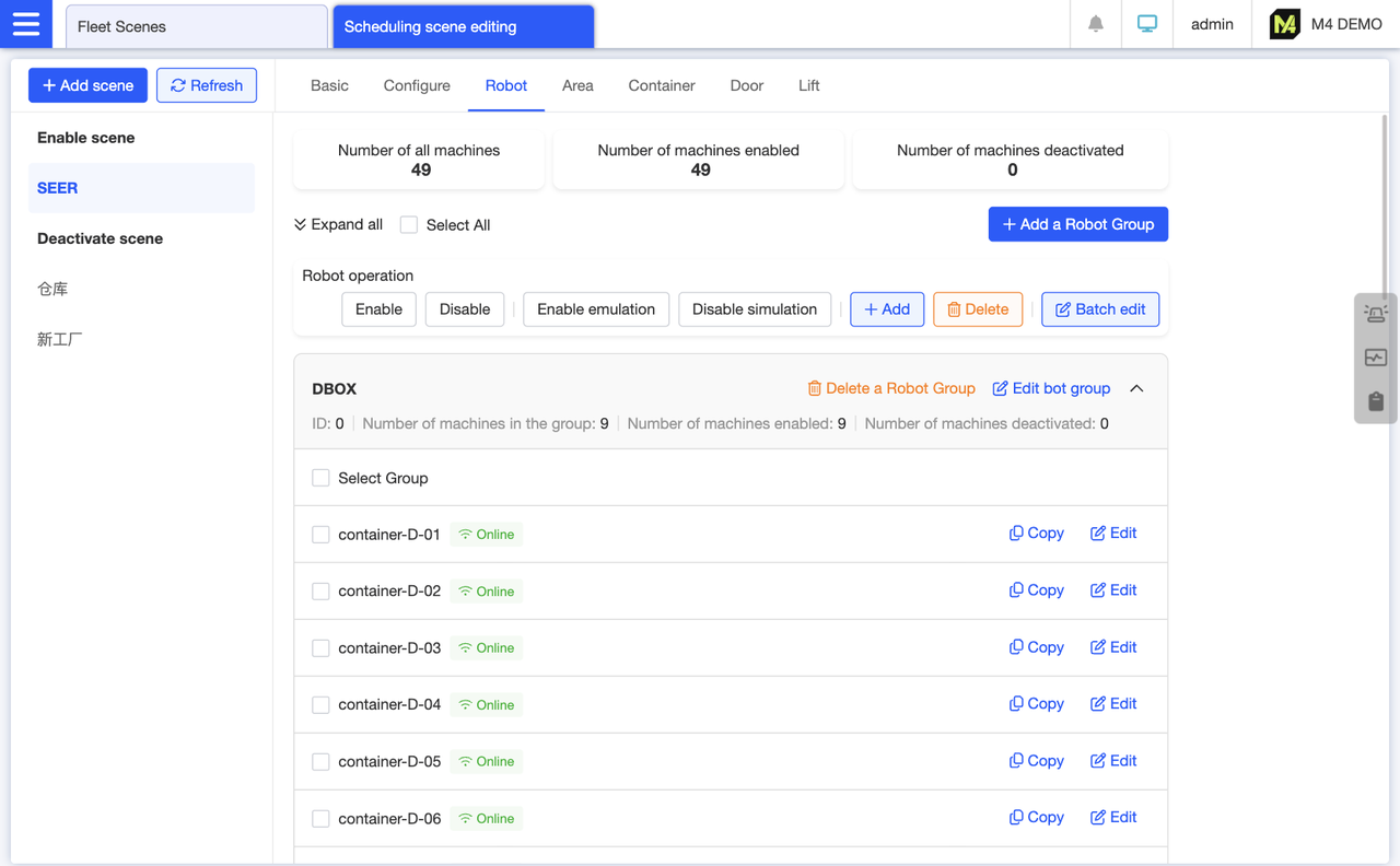
Group view displays all robots in the scene, supporting batch addition and duplication of robots. After selecting robots, click the action buttons at the top—such as “Enable” or “Disable”—to perform batch editing.
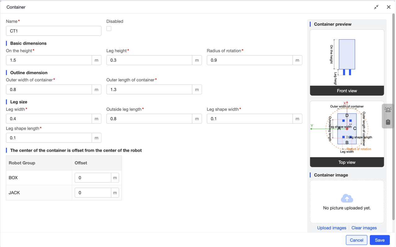
To add a container type to a scene, you need to configure the base dimensions, outer contour dimensions, and leg dimensions. Beyond these fundamental parameters, if the container is not positioned at the robot's exact center, you must also configure an offset. For ease of understanding, all configuration values include default settings, and the preview image on the right labels the meaning of each value. This visual reference makes configuration simpler. As you input configuration details, the container preview on the right updates in real time.
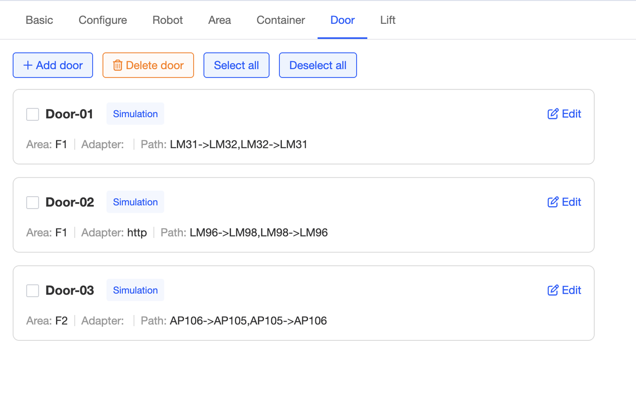
Supports configuring multiple doors within a scene. Once configured, the card displays the path and zone where each door is located. In simulation mode, doors will be marked with an identifier.
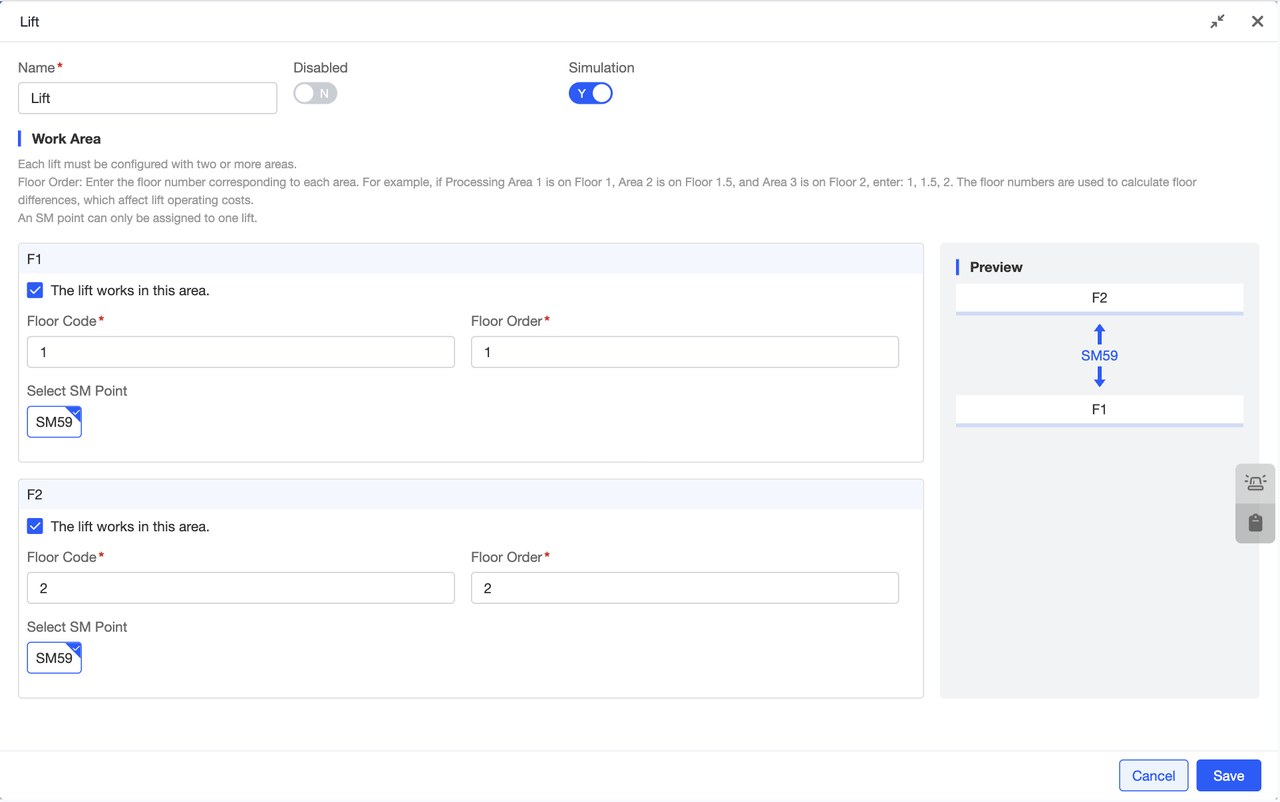
Configure lifts for the scene by selecting the area where the lift is located. Within that area, configure the lift's floor coding and floor sequence. Select the SM points for the lift within the scene. The preview on the right updates in real-time based on the configuration, simulating the actual lift distribution for a more vivid representation.
Copyright © 2025 SEER Robotics Europe GmbH.